Whether you are building a custom mechanical keyboard or troubleshooting your mechanical keyboard’s switches, knowing how to test keyboard PCB is a must. One common method for testing keyboard PCB is to check for ghosting. Ghosting occurs when multiple keystrokes are registered as a single keystroke, which can be a frustrating issue for mechanical keyboard users. What is keyboard ghosting explained? It is the phenomenon where certain combinations of keys are pressed simultaneously and the keyboard fails to register all the key inputs. Knowing how to test for ghosting and other keyboard issues will help ensure that your custom mechanical keyboard or troubleshooted keyboard is functioning at its best.
In this article, we’ll guide you through the process of testing your mechanical keyboard PCB to identify and resolve any issues.
By following these easy steps, you can ensure that your keyboard is working smoothly and efficiently.
So, let’s get started!
Tools Required To Test Mechanical Keyboard PCB
Here are the tools you would require:
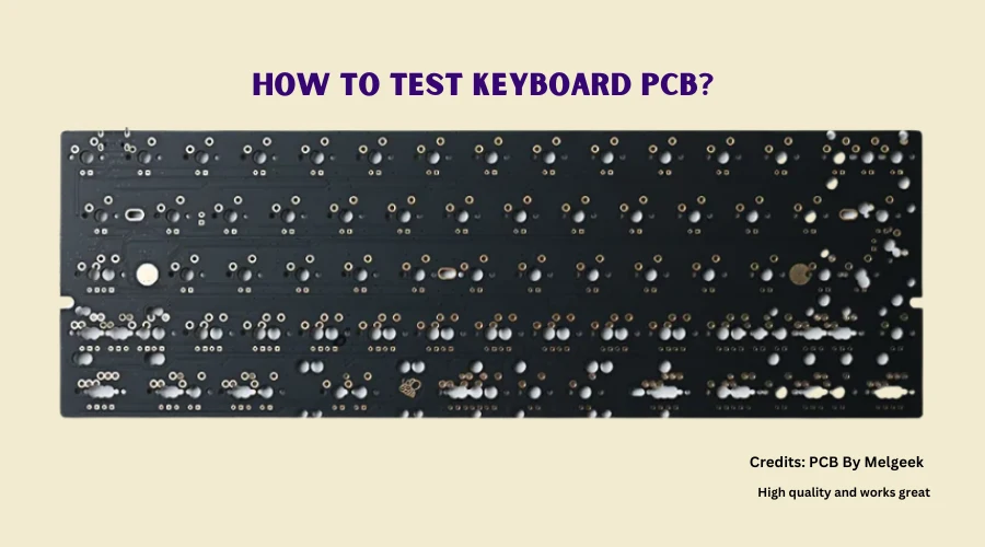
1. PCB
An easy PCB(Printed Circuit Board) can be made using a computer and a solderless breadboard. In any case, you need a PCB to test the circuit board.
2. USB Cables
You need a compatible USB cable with your PCB. The USB port on your PC is not the same as those on your PCB.
You have to check for their compatibility on the PCB verification sheet. If this doesn’t serve you should call your PCB manufacturer for further details.
3. Switch Testing Software
Use VIA software if your PCB is compatible. You can use it as many times on your computer since it is a downloaded program.
This is easy to use as it comes with multiple features offering a list of tools for your help. You need to figure out another option if your PCB is not compatible with this software.
4. Metal Tweezer
Use a very good quality of metal tweezer that has a strong grip on your fingers. You have to be confident in not losing them and go steady with their use on the circuit board.
How to Test keyboard PCB?
To test keyboard PCB, first clean the surface of the board, then connect it to your PC using a USB cable and open your switch testing software such as VIA. Finally, test individual switches and ensure proper connectivity of all the pins.
Here are the detailed steps below:
Clean PCB Surface
First and foremost you have to wipe down your PCB using a lint-free cloth to ensure the board is free of dust, debris, and contaminants.
Cleaning up your PCB board is necessary for clear visibility of the markings in it.
Connect your PCB to your PC
Connect your PCB to your PC using the USB cable. It will communicate to the PC using SPI(Serial Peripheral Interface), RS232(Recommended Standard 232), CAN(Controlled Area Network), and LIN(Local Interconnect Network) protocol.
With serious observation, you have to plug in the cable to your computer with the other end into your PCB.
Check out for an LED light on your PCB and plug it into the back of your computer. The LED illuminates while your computer is running. This cable is blue in color with a yellow stripe. Connecting PCB to your computer is actually quite simple.
Open PCB Switch Testing Software
Your next step should be opening up your PCB in the VIA Software and following this open up the Test Matrix. The Test Matrix shall assist you in identifying what needs to be tested on your PCB. You can now set up the test by setting the mechanical keyboard and starting testing.
Make sure to choose the keys you want to test while testing your mechanical keyboard. Set the keys you prefer to test using the Test Matrix.
In no time the Test Matrix will help you point out the keys and the wires they are connected to.
Test the Individual Switches
It is necessary for you to have a quick test on each switch on the PCB before assembling the board. It shall give you surety about the functionality of the keys and proper connectivity of all the pins. You will notice a light on pressing the switch.
However, you can exchange or re-connect the switch if you find the keypad is not working. Don’t miss out to check on switches that are used for backlight. If this doesn’t work then sadly the keys on the PCB are not working rightly.
Check out maintaining rows and columns, and testing each switch. In certain PCBs, there are many pads side by side.
Things You Need to Check While Testing Mechanical Keyboard PCB
Check for Continuity
Electrical continuity of the PCB can be done with continuity testing by connecting a multimeter to each component and measuring the resistance between the two.
The components are not connected properly and need re-soldering if you find the reading more than the expected value
Check for Common Faults
Common faults could be many while you are testing your PCBs. Check out for any defects or breaks in the circuit. Perhaps any physical damage. The cleanliness of your PCB should be a consideration.
Any dirt, dust, or corrosion might cause a fault leading to major obstruction. Another fault could be in the solder joints with a crack or break. Make sure that the components are soldered properly to the board.
Be sure to check the power on the PCB. All components should be properly connected to avoid voltage leakage in the circuit.
Finally checking on the functionality of the keys by pressing each key one at a time is important. Replace or repair any key that is malfunctioning on your mechanical keyboard.
Check the PCB Test Points
An exposed copper pad used to check the specific functioning of a circuit is a test point in a PCB. To detect potential issues, test signals are injected through the test points. Optimal changes can be made with the desired results which the test signal output determines.
The PCB test points should be on the exterior layer of the board with its contact with the equipment probe so you can conduct a test. However, a perfect PCB Test Point allows you to have smooth testing of your keyboard PCB.
How do I know if my keyboard PCB is working?
There are a few troubles to provide accessibility in the smooth functioning of your PCB. Checkout our list for the minimal issues:
PCB not recognized by Windows or disconnect in use
Test the USB cable/port. Try to use a different USB port instead of a USB hub. Your PCB might not be getting enough power from the computer.
PCB is in DFU mode/bootloader
Bring the switch on the back of your mechanical keyboard in position and unplug your keyboard. Plug it back in while the switch is in position.
Loose or improper connection on the USB port, JST header, or JST cable
Make sure to seat your USB cable properly. A wiggling USB cable might also cause disconnection. Checkout for kinks/bends on the cable as the bent pins on JST male cable can also cause interference.
Check for bent pins inside the female JST port as well. Be sure that all the pins on the JST female port are soldered in place.
However, if any specific keys are not registering, test the connection by bridging the pads with tweezers. Remove the switch if the PCB is Hot Swap.
In a soldered PCB, triggering of the key while bridging confirms there is a problem with the switch and not the PCB. For a Hot swap PCB after trying 2 switches if the key triggers while bridging but not on pressing, in this case, the hot swap socket is the issue.
What causes a Keyboard PCB to fail?
There are certain factors that can lead to mechanical keyboard PCB dysfunction. Although the most common causes of PCB failure can be-
Defects
Defects mainly happen to be in a PCB assembly process. It might be a prevalent cause either. PCBs are sensitive to electrostatic discharge (ESD).
Component damage might result in the smallest discharge. It might suffer a downgrade of reliability or permanent damage. Some potential damages include Misaligned layers, short circuits, and crossed signals.
Precautions like ESD-safe smocks, shoe grounders, and dissipative floor and work surfaces can eliminate the electrostatic discharge.
Burnt Components
- One of the major causes of PCB failure can be overheating or the board being exposed to extreme heat or direct flame can increase the defect. PCBs can withstand a glass transition temperature(Tg) of 170 degrees Centigrade and an operating temperature of 25 degrees centigrade which is less than Tg.
- Tightly packed component spacing or if the components are too close on the circuit board it provokes overheating. This can impact the performance of adjacent parts. The optimum amount of space is crucial to avoid this defect.
- Technical error or a component failure can risk your PCB from burning out. The board should be hooked up correctly to allow the voltage protection at par. A technician error can be alleviated with a hook-up detailed instruction.
Environmental Factors
Heat and humidity or other environmentally sensitive factors can cause an expansion in PCBs. These conditions might damage soldered joints. PCBs are generally manufactured in a climate-controlled environment.
Debris like dust, hair, liquid, and fibers can also have adverse effects on your PCB. At times these dumplings lead to overheating.
Soldering Factor
Solder as a key factor maintains contact between the component and circuit in a PCB. A conductive short circuit can result from excess moisture in the solder. Contamination can lead to board failure.
Some common traits of solder defects could be Opens, Excessive solder, Component shifting, Cold joints, Solder bridges, Webbing and splashes, or Lifted pads.
Human Error
Not very obligatory, but human error can be a vital cause of PCB failure. Any shortage of conviction while PCB production can get wrong on its smooth functioning.
Such lack of quality production can result from misreading a schematic, incorrectly installing components, or placing traces close which can cause short, poor soldering, etc.
However, these errors can be fixed with efficient time and money.
Expiring Limits of Service/Age
PCBs tend to break down with age. After an expected time period of usage, a PCB must be fixed or replaced with a new one. PCB manufacturers offer after-market services that can serve your exchange purpose.
What is a Keyboard PCB?
A keyboard PCB, or Printed Circuit Board, is the backbone of a keyboard. It’s a thin board made of insulating material, such as fiberglass or plastic, that has conductive pathways etched onto it.
The PCB connects all the components of a keyboard, such as switches, diodes, and LEDs, and allows them to communicate with the computer. The design and layout of the PCB determines the physical layout and functionality of the keyboard.
Through Hole PCB
This is actually a manufacturing method of PCBs in which through holes are used instead of plated through holes. The internal circuits in these PCBs are formed in a core material made from epoxy resin or polyimide.
Drilling a plurality of through holes on the surface of the core material is processed in these PCBs. Later an inner conductor layer is formed in each through hole. This results in forming an external conductor layer on the outer surface of the core material as well.
Standard PCB
A flat, thin sheet of insulating material with conductive traces on both sides forms out to be a standard PCB. Integrated circuits, resistors, capacitors, inductors, and other devices are supported and interconnected through PCBs.
A non-conducting substrate is laminated with one or more layers of copper foil. PCBs are produced by forming multiple layers of alternating insulating and conductive material on a fiberglass sheet using laminating machines with automated tape.
After cutting into discrete panels, these materials are drilled with a series of through holes subsequently.
Hot-Swappable PCB
These are electronic components with a PCB and a set of electrical contacts which are replaceable without taking the trouble of dismantling the entire PCB.
It allows easy installation, removal, and replacement of modules without disrupting the operation of the device or causing any damage to the circuit board.
Since power supplies demand operation over conditions like load, temperature, supply of voltage, or operating frequencies. Hence, this Hot Swap technology was enhanced for power supplies and power distribution systems.
They are designed to supply a stable voltage and current. A power supply converts and transmits electrical power from a source to the desired level of voltage and current.
Some Dos and Don’ts while Testing PCB
You should be very careful while handling your PCB. Recklessly working on circuit boards can lead to unintended damage and make them useless. Faulty implementation might disrupt the effective functioning of your circuit board.
Certain precautions might save your PCB from damage:
- Avoid exposing copper traces to air that may become contaminated by oxidation.
- Avoid debris while you are working on your PCB. However, due to its size, identifying dust may be hard but keep arranging a dust-free environment for your PCB testing.
- Wear protection gloves while you work on circuit boards to avoid contaminations like dirt, sweat, etc. Avoid using material where strings may fall on the board for any purpose.
- Avoid condensation by testing your PCB in a ventilated testing environment with a controlled temperature.
- Using proper tools while working on circuit boards is very important in order to avoid any physical damage while you are working manually on it.
Is it better to Repair or replace a defective PCB board?
It is quite possible to repair PCBs these days to make them fresh again. A repaired PCB can be used in the original device where it belonged to or you may use it in some other device further recycling it.
Replacing your PCB is always beneficial specifically if it is an OEM. It can restore the function of your electronic device to its original specification. To meet the updating industry standards for safety equipment, medical devices, and avionics, replacing PCBs is advisable.
Suggested Read: How to Build a Custom Mechanical Keyboard?
Frequently Asked Questions
Is it OK to touch PCB?
Can a damaged PCB be repaired?
Can static ruin a PCB?
Can you use a toothbrush on a PCB?
What is the life expectancy of a PCB?

I’m Anirban Saha, Founder & Editor of TechBullish. With a B.Tech in Electronics and Communication Engineering, and 6+ years of experience as a software developer, I have expertise in electronics, software development, gadgets, and computer peripherals. I love sharing my knowledge through informational articles, how-to guides, and troubleshooting tips for Peripherals, Smart TVs, Streaming Solutions, and more here. Check Anirban’s Crunchbase Profile here.